Permaculture Design Companion
The Permaculture Design Companion is a practical 190 page workbook that uses permaculture tools to bring your project to reality.
-o-
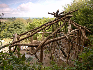
Timber Frame
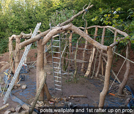
The frame is constructed from quite wiggly round oak logs 5"-10" in diameter. All of these were selected and felled from the surrounding woodland as part of an ongoing program of thinning to allow selected trees space to grow on to maturity.
 The
basic construction is a series of vertical posts in an oval, the tops of
which are connected with horizontals. This ring of horizontal pieces makes
what is conventionally refered to as a roofplate or wallplate. The horizonals
are 'tennoned' into the posts although a simpler alternative is to 'half
lap' the horizontals and use a metal bar / big nails to fix the joint on
top of the post.
The
basic construction is a series of vertical posts in an oval, the tops of
which are connected with horizontals. This ring of horizontal pieces makes
what is conventionally refered to as a roofplate or wallplate. The horizonals
are 'tennoned' into the posts although a simpler alternative is to 'half
lap' the horizontals and use a metal bar / big nails to fix the joint on
top of the post.
 Please
note that all of the frame was made with the bark left on. Better practice
for longevity is to remove the bark. I like to use a spade and sharpen it
up a bit.
Please
note that all of the frame was made with the bark left on. Better practice
for longevity is to remove the bark. I like to use a spade and sharpen it
up a bit.
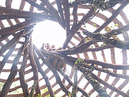
Reciprocal Roof
Once the posts and wall were up, a reciprocal roof was built on top. The reciprocal roof is fun and easy to make and ideally suited to round wood construction with a minimum of woodworking and structural complication (It doesn't push outwards on the walls and doesn't require tie beams). It also looks damn fine. Getting your head 'round it can be a bit tricky so i'd recommend having a go with a few small sticks before trying the real thing.
To make a reciprocal roof, the first rafter is propped up temporarily (as in picture above). The next rafter is then laid so that it sits on top of the first one. The third is then laid so it sits on the 2nd a little way down from where the 1st & 2nd cross. each rafter sits on another rafter below and has on sitting on top of it. This process continues all the way 'round until the last rafter just slips in underneath the first. The prop is then removed so the first rafter sits on the last one. Finally the rafters are fixed where they cross.
| How to Make a Reciprocal Roof : A bit more detail |
|---|
| Basically, you just temporarily prop up the top of the first rafter a little (=radius of central ring: see formulae) off the centre point of the essentially conical roof. When you are happy, lay the second rafter on top. Then lay on the third and so on. The distance between intersections or crossing points can be worked out (see formulae below) and also can be better checked by keeping the points where rafters touch all in a level plane, as you work round. The rafters should be fixed temporarily as you go. Nailing 2-3 foot of something between the rafter and the one previous, a little way down from the top seems best to me. When you get to the last one you should find just enough gap to squeeze it in. If its not quite right you should be able to jiggle the last few rafters a little to adjust the size of the gap. Once they are all in you just need to take the prop out from under the first. This is the exciting bit. Hopefully you hear a creak and the inner ring drops by about and inch or two. I would strongly recommend doing this with a lorry strap or a good rope tied round the outside of the inner ring and left there until final fixing is complete. Though it barely needs it, fixing the rafters together is recommended. I used inch diameter wooden pegs although rebar, nailtape, 6 inch nails or cat gut are all good alternatives. |
| Some useful formulae for reciprocal roofs |
| Gradient = vertical dist. / horizontal dist. = tan (pitch) |
| Wall post height = height of central ring - (dist. from centre x gradient) |
| Distance along rafter between previous and next crossings in the central ring = Diameter of rafters at central ring / gradient |
| Diameter of central ring = (No.of rafters / 3.14) x Distance along rafter between previous and next crossings in the central ring |
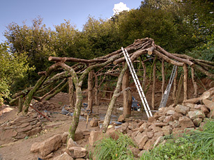
 In
this case, the reciprocal roof is made on an oval, rather than circular
wall. The centre is also offset to allow a higher wall on one side whilst
keeping the same pitch on all main rafters (see elevation).
This allows the building to more naturally follow the line of the hillside
and is in keeping with trying to maximise diversity of the internal space.
Wall posts were located where equal angles from the roof's cente point crossed
the desired wall line. Post heights were then calculated from the measured
distance to the centre point and the desired pitch or gradient.
In
this case, the reciprocal roof is made on an oval, rather than circular
wall. The centre is also offset to allow a higher wall on one side whilst
keeping the same pitch on all main rafters (see elevation).
This allows the building to more naturally follow the line of the hillside
and is in keeping with trying to maximise diversity of the internal space.
Wall posts were located where equal angles from the roof's cente point crossed
the desired wall line. Post heights were then calculated from the measured
distance to the centre point and the desired pitch or gradient.
Lean-To's
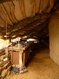 After making the
roof we added 3 lean-to covered areas againt the sides of the building where
there were no windows or doors. These fullfilled 4 functions:
After making the
roof we added 3 lean-to covered areas againt the sides of the building where
there were no windows or doors. These fullfilled 4 functions:
- more covered space (indoors outdoors)
- aesthetic (house built into the ground look)
- sheltering the house from weather
- structural strength (not really necessary but always good)
In their simplest form these were just made by fixing more logs from the top of the wall plate down to the ground where they sat on slightly dug in stones. At the front of the building they were a little different with a section of posts and beams as per walls. At the door this joined into an arch made of two curved logs.
![]()

This work
is licensed under a Creative
Commons Attribution-Noncommercial-Share Alike 3.0 License. For high
resolution images, please click here.
Except where specified, all writing on this website is written by me and purely represents our own opinion. Whilst it is all written with an open heart and best intention.